Common Bending Issues

1. Flattening of the tube cross-section

During a bend, a lot of force is applied to the tube. Sometimes this force is enough to forcibly alter the shape of the material, often resulting in the tube diameter becoming distorted. This can be seen as an oval tube after bending, and is sometimes referred to as the tube collapsing.

2. Lump on outside of the tube (pressure die side) at the end of the bend

This is usually caused by the internal mandrel body being positioned too far forwards during the bend. Moving the position backwards should allow the material to flow over the tip of the mandrel body more easily, and thus reduce the bump.

Sometimes if the mandrel being positioned forward is required during the start of the bend, the use of ‘Phased Mandrel’ to allow for early mandrel extraction before the bend completes can also help to alleviate any issues with a bump forming.

3. Lump on inside of the tube (bend die side) at the end of the bend

This is usually caused by the internal mandrel body being positioned too far back during the bend. Moving the position forwards should allow the mandrel to better support the inner face of the tube, and help to prevent this bump.

4. Wrinkles on inner side of the bend

The stability of the inner tube wall is lost during the bend. This is usually caused by an incorrect tool setup, whereby the tube has space to expand/wrinkle into. Generally this can be alleviated by one or more changes to the tooling setup:

  1. Correct setup of the wiper die and mandrel
  2. Prevent tube from slipping in the clamp
  3. Increase amount of pressure applied from the Pressure Die.

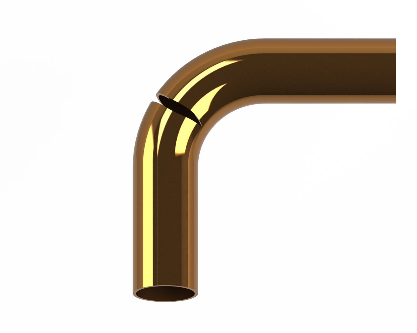
5. Tube is splitting/cracking on outside of bend radius

Sometimes it seems like a tube simply won’t bend, and instead has a tendency to simply crack or rip. It’s important to note here that there are two distinctly different types of breakage.

Firstly, a ductile material failure, this is seen where the tube has visibly stretched and thinned before eventually reaching breaking point.

Secondly, a brittle failure can be seen if the tube appears to have simply snapped. This is often quite abrupt, with little signs of the tube stretching. The edges of a brittle failure can appear clean and shiny.

Materials that are particularly hard tend to exhibit brittle failure, whereas grades of mild steel or the 300 series stainless steels tend to bend more easily, but could be prone to ductile breakage in certain situations.

The solution is simply to prevent the outside of the tube from stretching beyond its limit. We recommend ensuring a heavy drawing lubricant is used on the mandrel to prevent metal on metal resistance. You should also ensure the mandrel is not positioned too far forwards, as the tube cannot bend around the mandrel body if positioned incorrectly, and this can cause breakage. It can also be the case that the tube is being squeezed too hard by the pressure die, preventing material from flowing, this may need backing off a little.

If the above are not successful, it might be that the amount of pressure die assist should be increased, or on some machines it may be possible to boost/push the end of the tube. These changes will help to push material into the bend, and reduce the stress on the outside of the bend.

Should any of the changes above solve the cracking issue, but introduce other problems, you should fault find these issues separately.

6. Outer Wall Thinning

Firstly, it should be noted that tube will naturally thin on the outside of the bend during the forming process. If the thinning is too much to be acceptable for a particular application, there are some methods for attempting a reduction in the thinning.

Usually the most reliable method of doing this is to have a means of ‘boosting’ the tube during bending. This can either be done by increasing the amount of push that is provided by the Pressure Die Assist mechanism, or on some machines an even better solution is the use of a booster clamp that physically grabs hold of the material and forcibly pushes it forwards during the bend. This extra pressure in the forwards direction during the bend, helps to relieve pressure on the bend.

7. Material Springback

Most materials will not bend, and then stay in the same position after bending. Generally the material being bent will have a level of elasticity, and when the clamps are released, the tube will relax slightly.

Usually this causes the angle of bend to reduce once the part is released. For example if a machine performs a bend of 90 degrees, once the part is unclamped and released it would not be unusual to see a product with 88 or 89 degrees as the final bend angle.

The easiest way to compensate for this, is simply to over bend to begin with. If a perfect 90 degree angle is desired, then the machine may need to be programmed to produce a 91 or 92 degree bend, that will relax back to give a final position of 90 degrees.

The amount of springback that is exhibited, will generally vary from material to material, and is often seen to vary even within different batches of the same material.